
Innovation thrives on collaboration and teamwork. However, in many engineering organizations, over-reliance on just a few individuals can lead to bottlenecks and slow progress. This, coupled with the complexities of data sharing and collaboration, can pose significant challenges. While software developers have demonstrated the advantages of scrum methodologies, creating truly integrated simulation teams that enable most team members to share most tasks remains difficult.
In the Simcenter Mechanical simulation 2312 release, we introduce additions that extend and integrate workflows from the designer through simulation and all the way to the physical tester. We provide new tools to simulate e-machines for electric vehicles and improve simulations for automotive safety. We have sped up simulation performance and further integrated NX and Simcenter 3D to improve collaboration and shorten development cycles.
Simcenter Mechanical simulation software can help get the answers you need before ever building a physical prototype. Simcenter Mechanical tools let you model the complexity of your products, help your development processes become faster, explore more possible design options, and keep your simulation data and processes integrated.
With those pillars in mind, development highlights for this year are focused on these key themes:
- Streamlining Electric Vehicle Powertrain Development
- Integrating physical tests and simulation
- Driving design with simulation
- Simulating additive manufacturing
- Improving automotive safety
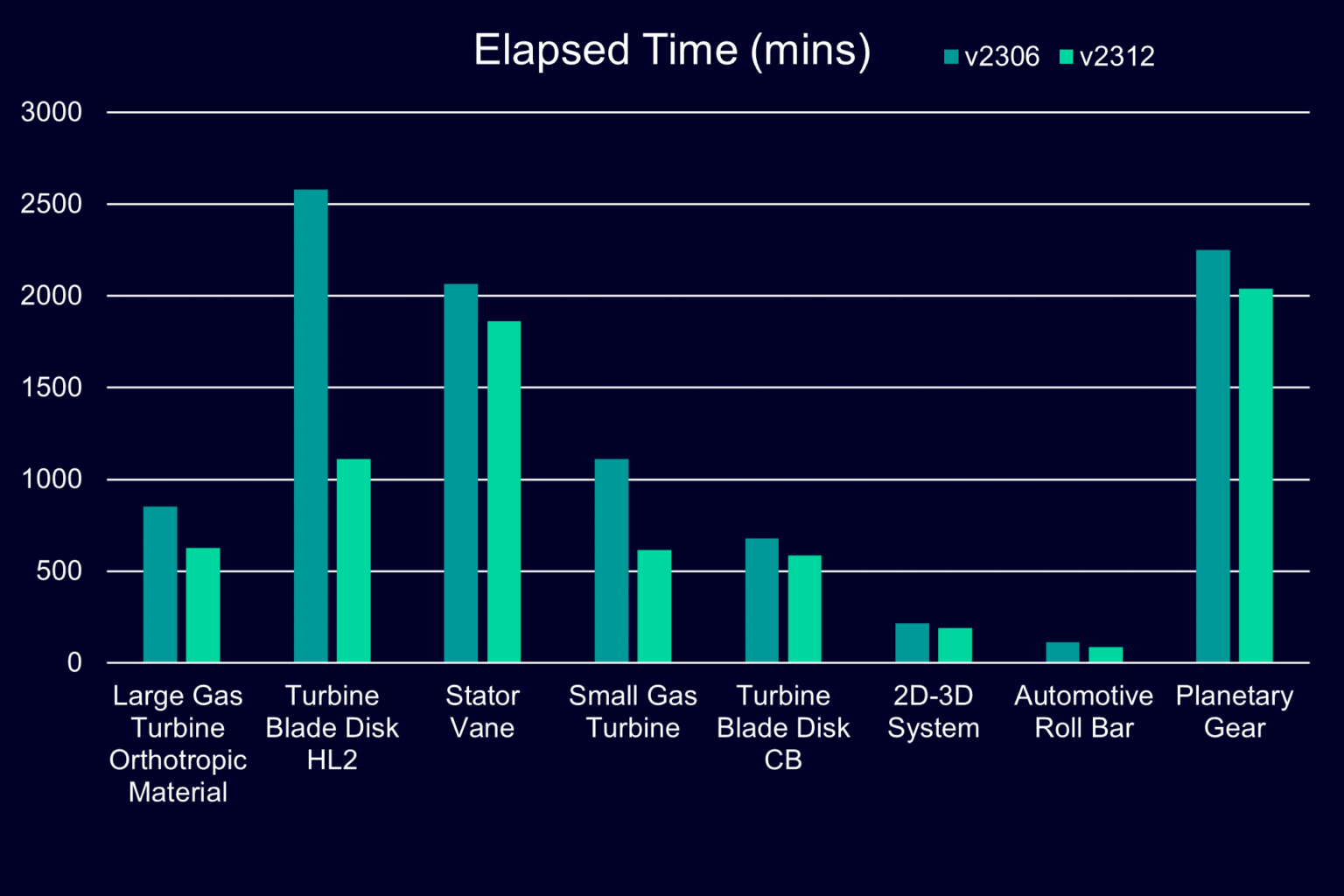
- Speeding simulation performance
Streamlining Electric Vehicle Powertrain Development
According to the International Energy Agency, over 10 million electric cars were sold in 2022. This accounts for 14% of all new cars, up from just 5% in 2020. To increase EV range manufacturers continuously look for ways to remove weight.
Introducing the new Simcenter E-Machine Design software
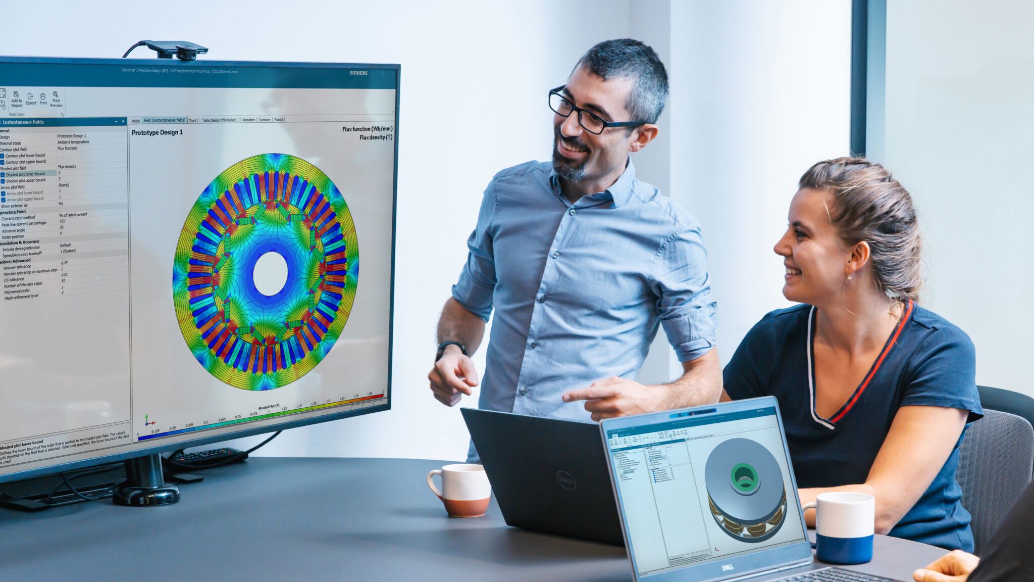
 New to the Simcenter Mechanical family of products is the Simcenter E-Machine Design simulation software. This new product brings together the best of the existing electromagnetic solutions into one package. The ease and convenience of parameterized templates with 2D models including axial flux motors and the detail of Multiphysics simulation in 3D models are both available. It is fully integrated into the Simcenter family enabling you to continue your analysis in other domains.
Find out more about Simcenter E-Machine Design simulation software in our latest podcast where our host interviews the Simcenter E-Machine Design Product Manager to discover its best features.
Simcenter E-Machine Design: Axial flux motor design
Since axial flux motors can produce a similar performance to radial flux machines but are smaller and lighter, they are an obvious solution to reduce weight without losing performance. However, it can be harder to dissipate the heat generated by axial flux machines, and accommodating the air gap can be difficult. The complex nature of these machines is challenging R&D departments, many of whom are starting to use simulation tools to reduce development costs and time. Simcenter E-Machine Design can help you quickly design an axial flux motor that meets your performance requirements.
Simcenter E-Machine Design / Simcenter 3D: Transfer electromagnetic forces for vibro-acoustics simulation
Electromagnetic forces can significantly impact the structural or acoustic response of an E-Powertrain.
You can take the electromagnetic forces calculated in Simcenter E-Machine Design and then easily transfer them to Simcenter 3D. For example, a common use case for this is to take the loads produced by the motor as output and use it as the input for the powertrain transmission as part of a NVH analys.
Simcenter 3D Motion: Compound planetary gear definition
With Simcenter 3D 2312, NVH analysis can now be investigated with greater detail than ever before thanks to the inclusion of a gear type that can withstand high loads, the compound planetary gear. Furthermore, with the new cyclic symmetry feature in Simcenter 3D, analysis of the motor, and its outputs is significantly faster as shown in this video.
Integrating physical test and simulation
In order to run a physical test for a product or component, the test subject needs to be fitted with a number of sensors that are often expensive, such as strain gauges, at key locations. However, what if the part’s geometry is complex or if a critical section that needs to be measured is in a very hard area to reach in the finished product? It can be impossible to get a physical sensor in that location, making it impossible to know if your product will survive critical load cases.
Despite an engineer’s best efforts, placing a sensor on the desired location can often prove impossible. Furthermore, including many sensors in a test can add significant time and cost to the testing procedure. What if we could blur the lines between simulation and physical testing?
Introducing Simcenter 3D Smart Virtual Sensing:
Measure the unmeasurable
In this release, Simcenter 3D introduces Simcenter Smart Virtual Sensing software. Smart virtual sensors take the FE model of the product and boils it down to a reduced order model so that it can be run in real-time alongside a physical test via a functional mock-up unit (FMU). During the test, you outfit your test subject with just a few strain gauges in easy-to-reach areas, which then feed information to the virtual model in the FMU. Based on data coming from the physical strain gauges, the reduced order model calculates the operational loading conditions the part is experiencing and then solves the model to calculate results at your virtual sensor at the critical location.
Executable Digital Twin (xDT)
Another highlight of Simcenter Smart Virtual Sensing is real-time capability. This real-time capable virtual model of your physical structure is what Siemens calls the executable digital twin, or xDT for short, and this opens the door to fascinating applications. For example, you can use the xDT during a physical testing to reduce instrumentation time and cost of physical tests by reducing the number of sensors and therefore the time needed to outfit the test subject or to measure real loads in operational conditions.
Additionally, the xDT can live on edge devices on your factory floor to sense when something may need to be adjusted to the manufacturing process, the machine, or the part you’re producing. Smart virtual sensing can also be implemented out in the field for predictive maintenance purposes.
Driving design with simulation
Simulation is no longer just a performance validation tool. Simulation is becoming an organic part of the design process by leading manufacturers to discover and produce new, unimagined design possibilities.
Upfront Simulation can help designers create better, more robust designs, while also speeding the overall time it takes to complete a revision – meaning faster time to market. Upfront simulation is also a tool to improve communication between the designer and the engineer.
NX Performance Predictor
This year we introduced a new product called NX Performance Predictor which Designers use to provide design guidance without having to throw it over the wall to the CAE group and wait.
This new tool works within the NX interface but is based on the proven technology from the Simcenter solutions.
Designers can now apply loads and constraints to their parts to simulate linear static and natural frequency analysis. The rapidly returned results even include a safety factor to help designs assess the risk of part failure. Further design edits are reflected in the automatically updated simulation results, so the designer can quickly see the effect of their design change on performance. When complete the design and simulation results can be sent seamlessly to an engineer for further analysis and validation.
NX Topology Optimizer: 3-Axis CNC tooling shape constraint
NX Topology Optimizer has been available for a few years now, and one new exciting feature introduced this year is the ability to define a shape constraint for parts that will be manufactured using CNC 3-axis machining. This new capability allows the designer to account for tool length and tool diameter during optimization to ensure the end geometry result can be created by a CNC machine. Additional manufacturing constraints are available for both additive and subtractive manufacturing processes.
Introducing Simcenter 3D Design Space Explorer
Developments in simulation tools and the growing complexity of products are continuously increasing the possibilities that an engineer can investigate. Often the product’s performance can be considered from the perspective of multiple disciplines each of which can be affected by numerous independent parameters or any combination. Therefore, selecting the best parameters to optimize the results at any given stage of a design space exploration study can be difficult or even counterintuitive, and thus a true randomized study may in fact be optimal.
New this year is Simcenter 3D Design Space Explorer. This new module is integrated natively within the Simcenter 3D environment for end-to-end associativity. What this means is that the design parameters, simulation model, and results are all associated together for the most efficient process. You can easily set up an exploration objective that automatically modifies design parameters, updates the simulation model, and re-runs the simulation without needing manual intervention. Now you can run tens to thousands of iterations to evaluate tradeoff scenarios or perform design optimization on specific criteria.
Simulating additive manufacturing
Additive manufacturing is changing and expanding the types of geometry that you can create for your products. This results in unique and lightweight designs. However, the process of getting your parts to print correctly can be a costly time-consuming, trial-and-error, endeavor. This is because the repetition of localized heat required when printing metal parts causes the geometry to deform – meaning the shape of your parts doesn’t match what you designed in CAD.
Simcenter 3D Additive Manufacturing: Unified high quality STL based compensation
In this release, Simcenter 3D has improved the compensation method for the Advanced Powder Bed Fusion solution to be more robust, faster, and easier to use. This means you can quickly compensate your original geometry to account for the printing process so that your physical print will match your CAD geometry without going through a long trial-and-error process. Furthermore, in addition to the compensated mesh the support structure can also be compensated, then both can be read back into NX 2312.
Additionally, the interface has been updated so that managing large print data sets is easier, and print job data sets can be exchanged between users, including those using both the Simcenter 3D powder bed fusion solution and the advanced powder bed fusion solution.
Improving automotive safety
We have already discussed how simulation can be used in collaboration with physical testing to measure the unmeasurable, but for some engineers any testing on their test subject would be unethical. This is the challenge of safety engineers who are increasingly turning to simulation as an alternative to physical testing.
Electric vehicles (EV) can travel at high speeds almost silently, putting pedestrians at an increased risk. The performance of both active and passive safety systems is therefore critical. However, when testing accelerations that are likely to be greater than those that induce discomfort, test dummies are the only ethical approach, but these are expensive and not suitable for all applications. It is therefore essential that we simulate pedestrian impacts with a high degree of reliability to ensure new safety system designs are able to save lives.
Simcenter Madymo: Pedestrian human body models meets Euro NCAP TB024 v4.0 requirements
In the latest release of Simcenter Madymo, the TB024 family of human body models has been updated to ensure they are calibrated to the Euro NCAP TB024 latest (version 4.0) protocol. Compliance with this protocol ensures that these models can be used to simulate the effectiveness of Deployable Pedestrian Protection Systems (DPPS), such as an active hood.
Speeding simulation performance
As computing power continues to increase, I bet your simulation models continue to grow in size and become more complex. So it is important for today’s solvers to keep pace with technology and take advantage of parallel processing whenever possible to help speed up solution times to get the results you need faster.
Simcenter Nastran: Multistep solution times 10%-50% faster with SMP processing 
Our development team has made significant improvement to solution speed of the Multistep Nonlinear solution to take advantage of shared memory parallel processing – otherwise known as SMP.
In this release, Simcenter Nastran now uses SMP for the internal force calculation of plasticity and/or creep materials. When you request SMP with these materials, solution speed will be 10%-50% faster, depending on your model.
You can run SMP on a single machine with multiple processors and cores, and SMP does not require a special license.
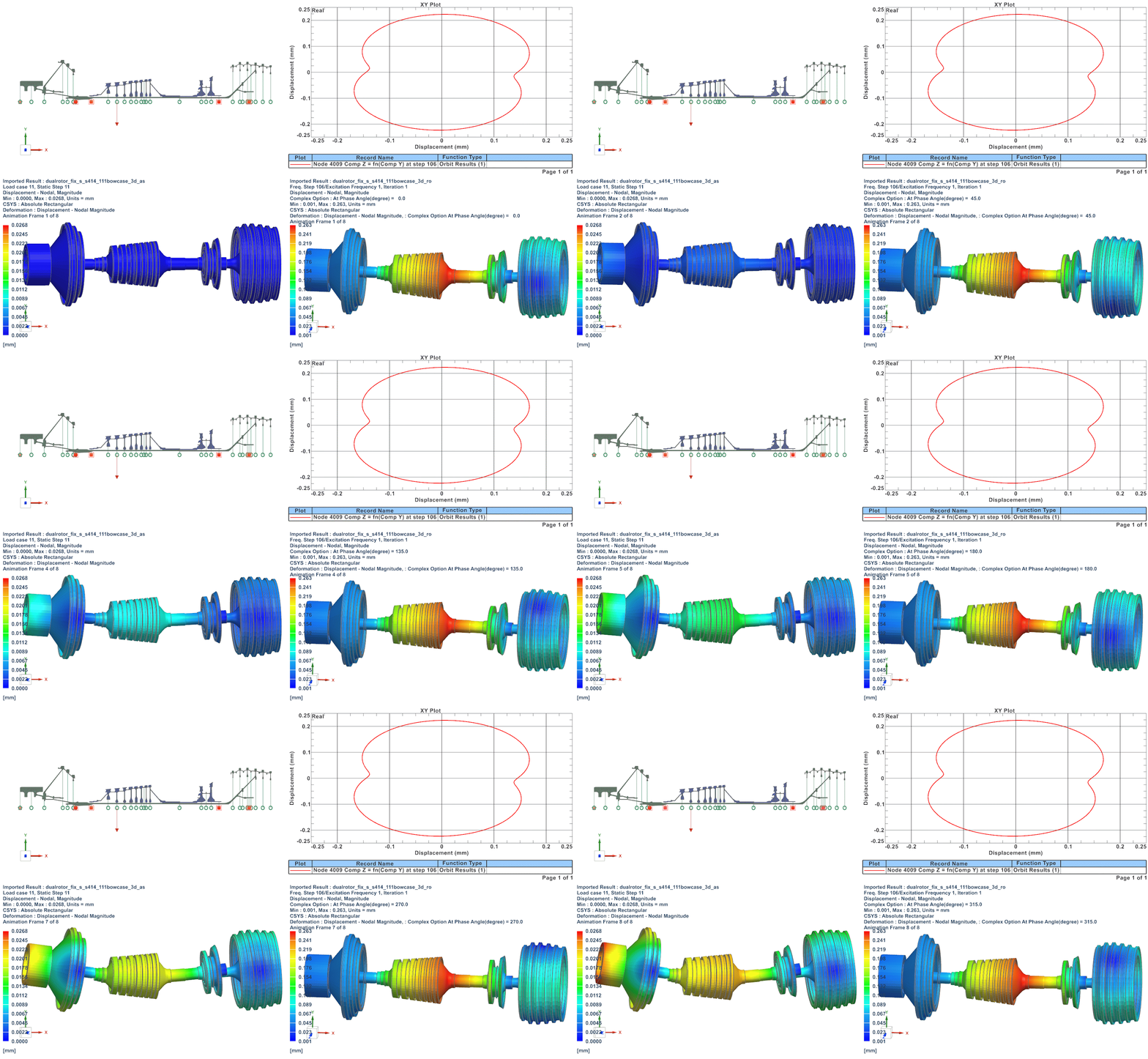
 Simcenter 3D Rotor Dynamics: Streamline your rotor dynamics workflow
Discover how Simcenter 3D Rotor Dynamics workflows can streamline the complete workflow from the definition of the geometry to the post-processing tools. How defects like unbalance or misalignment can be studied in a frequency range, and external loads can be applied as a function of frequency in the following blog.
Get working with Simcenter today
By Jonathan Melvin and Patrick Farrell


