
Model-Based Design Chain with Integrated Supplier Innovation
Integrated Model-Based Design Chains are becoming increasingly important as the ‘4th Industrial Revolution’ takes hold. This has led manufacturing companies in all industries to a bittersweet realization of the need for a major overhaul of their product development approaches that must include their supply chains – extending systems engineering into their design chains. A recent survey report by Deloitte shows that organizations that have holistic and comprehensively defined strategies for Industry 4.0 are already outperforming others financially. An integrated digital twin has been identified as one of the key technologies in enabling a successful transition to the Industry 4.0 paradigm. It becomes of utmost importance now more than ever for manufacturing companies to digitalize their product portfolio using digital twins that correspond to a virtual representation of a product in its entirety even before the first physical prototype is built and enhance the process and product performance thereafter. Model-Based Systems Engineering (MBSE) is a formal systems engineering approach that significantly bolsters the digital twin development of a product with an abstract system architecture model as the starting point.
A system architecture model developed in the early stages is one of the most critical aspects of MBSE that will drive the overall product digital twin development in industries in the coming years. This architecture model embodies multi-domain perspectives and can further serve as the basis for numerous domain-specific analyses. Today’s systems are indeed systems-of-systems, and the level of complexity of these systems along with the increasing numbers of disciplines involved make it inevitable to develop the system architectures in collaboration with the suppliers of the subsystems/components. Higher complexity and faster time-to-market demand that the supply chain is seamlessly integrated with the MBSE toolchain to improve the design process that has mostly been insular. Model-Based Design Chain (MBDC) is the extension of the MBSE enterprise to the supply chain, such that product architectures drive the design through the entire supply chain supporting a closed-loop product development process.
Not only from a process efficiency perspective, but the increasing influence of supplier expertise on product development has also proven time and again the numerous benefits it brings to design innovation. We are aware of the famous case from Chrysler Automotive from the 90s that demonstrated the benefits of supplier innovation to OEM product development, resulting from a few radical shifts in their supplier relationship strategies. More recently, the unveiling of Aston Martin’s AM-RB 003 hypercar leaves you in awe with its ‘aero-inspired’ wing design technology called FlexFoil that can morph its wing in place to optimize real-time aerodynamics, which is being developed by a supplier that traditionally supplied to aerospace manufacturers.
“It’s honestly a wild thing to watch in action, and I can’t wait to see it on Aston Martin’s new car.”
Sean O’Kane, The Verge
Glaringly so, this case reinforces the fact that modern customer-supplier collaboration in innovation is no more restricted within the bounds of their particular industries. These are not isolated examples. Clearly, there is a demand for a more streamlined approach to developing complex multi-domain products together with suppliers from traditionally different backgrounds, beginning in the early system design stages thereby front-loading critical supplier design decisions. Furthermore, the traditional OEM-supplier relationship as holistic entities will eventually need to be narrowed down to a product/design owner – supplier handshake for R&D collaboration.

One way to enable such collaboration is by delegating specific parts of the system architecture models to the suppliers through an integrated framework that provides model sharing capabilities with lifecycle services. In the current MBSE practices, system architecture modeling has been isolated from the downstream development of subsystem architectures leading to inconsistencies and inefficiencies. At Siemens Digital Industries Software, System Modeling Workbench (SMW) for Teamcenter provides the ability to manage supplier innovation by enabling system-to-subsystem transitions of various modules of the architectures that can be shared with subsystem architects using a data orchestration platform like Teamcenter. The transitioned subsystem architecture entails the metadata conforming to the interfaces of the system model from which it was derived. An MBSE method can be applied to further develop these subsystems and the developed subsystem architectures can be integrated back into the system architecture through the concept of reusable libraries.
The following graphic shows a simple process flow for architecture collaboration and innovation.
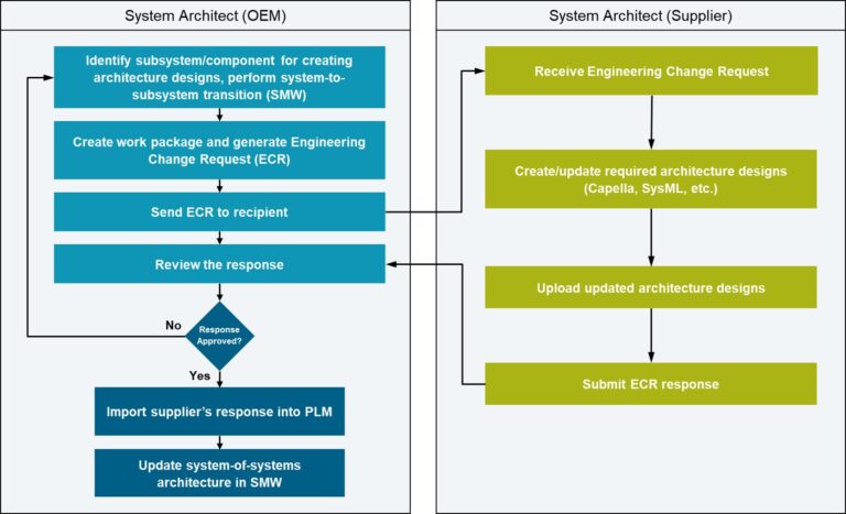
The process describes the interactions between the system architects within the OEM and supplier organizations in the context of a common PLM environment. This process is based on Teamcenter software’s supplier integration foundation. When the OEM system architect is ready to exchange data, an Engineering Change Request (ECR) is created for the supplier. The supplier system architect receives the part of the system architecture to be developed with necessary contextual information, develops the required architecture designs, and submits the developed design in the ECR. Upon approval, the OEM system architect integrates the subsystem design in the system (system-of-systems) model. The following case study from the automotive industry is a demonstration of the abovementioned process.
Case Study: Automotive OEM Active Park Assist Feature
Let’s consider the example of an automotive OEM-supplier use case for the development of an Active Park Assist (APA) OEM feature which is a part of the Advanced Driver Assistance Systems.
The case study describes the MBSE approach for incorporating a new vehicle requirement into the system architecture that eventually leads to the identification of a new component to be developed by a supplier and integrated back into the OEM architecture, wherein the transition to the supplier is integral to the creation of the digital thread along with increased process efficiency, faster development time and improved quality. The system architecture is defined in System Modeling Workbench using the ARCADIA method and the Capella notation. ARCADIA is a software and system architecture engineering method, based on architecture-centric and model-driven engineering activities. In this example, a new vehicle requirement is identified called ‘Pedestrian Detection & Protection’ and the OEM must incorporate this change into the architecture model.
1. Incorporating a new engineering change in operational analysis
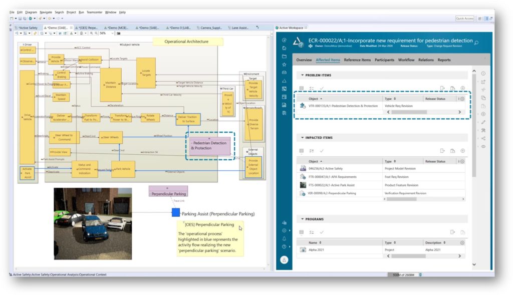
The image above shows the SMW client with an embedded Teamcenter Active Workspace window that displays the ECR. The operational architecture* on the left defines the interactions of the subject vehicle with the actors and entities that are involved during the vehicle’s operation. The new PLM requirement ‘Pedestrian Detection and Protection’ can be seen as trace-linked to an operational activity that fulfills the new requirement, through a simple drag and drop mechanism. In this way, the operational process chain (a set path among all possible paths traversing the dataflow) and the corresponding operational scenario (‘perpendicular parking’ verification scenario in this case) is updated if required.
2. Incorporating a new engineering change in system architecture
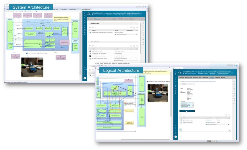
The newly defined vehicle requirement impacts the ‘APA Feature Spec’ and the feature requirements are updated simultaneously. The updated feature requirements are trace-linked to the system capabilities in ARCADIA and the corresponding system architecture is modified. The image above shows the system architecture and logical architecture in ARCADIA with the functional chains realizing (tracing) the operational process chain, initiating a functional digital thread. To satisfy the new functional requirement, the system architect has identified a new ‘Camera’ sensor logical component that must be requested from a supplier. At this point, the ECR for the new vehicle requirement is complete.
3. New OEM Engineering Change Request to request subsystem design
![]()
The OEM generates a new ECR to request the subsystem design from the supplier with all the associated requirement specs curated automatically using the Teamcenter traceability mechanism. Using SMW ‘system-to-subsystem transition’, the ‘Camera’ logical component is transitioned into a new system-level model such that the transitioned model inherits the linked requirements, interface information, allocated functions, and associated functional chains. The ‘Camera’ architecture model is added to the new ECR. This is a very powerful means of collaborating especially when it comes to protecting the OEM’s intellectual property. In the case of a supplier using a preferred modeling methodology (SysML language for example), the interoperability mechanism in SMW can enable exporting the Capella model into the desired format thereby promoting an open and extensible collaboration workflow.
4. Supplier model development
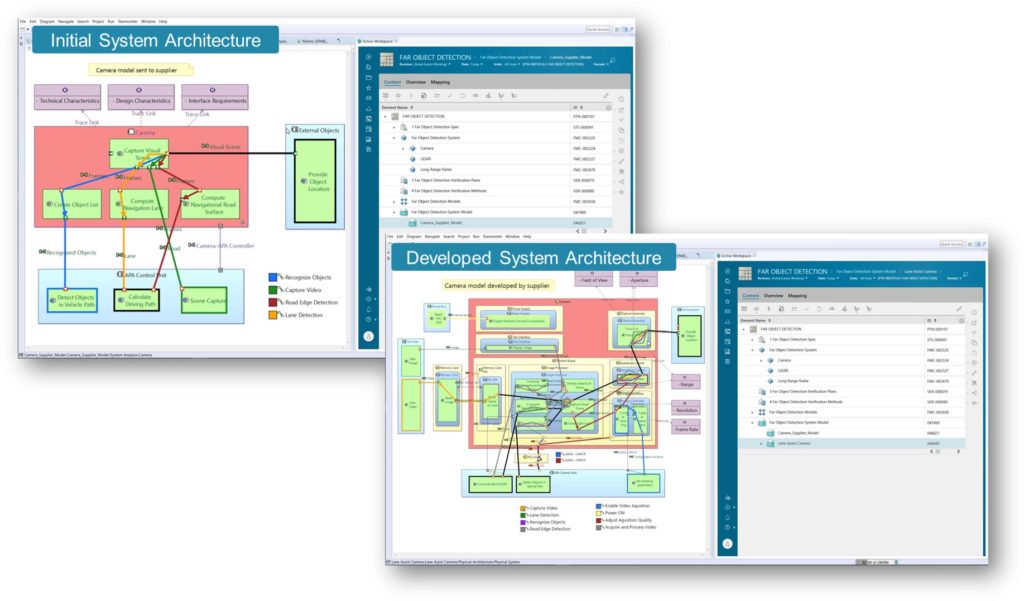
The supplier opens the ECR, accesses the curated data from the shared Teamcenter environment, and downloads the subsystem architecture model from Teamcenter for further development. The architect then details the subsystem architecture based on the ‘Camera Spec’ defined by the OEM and provides the developed model back to the OEM through the ECR. The supplier model is developed within the bounds of the interfaces defined initially to maintain consistency. However, any modifications or changes to the camera interfaces if required could be allowed based on a well-defined change workflow.
5. Integration of the developed supplier model in the OEM model
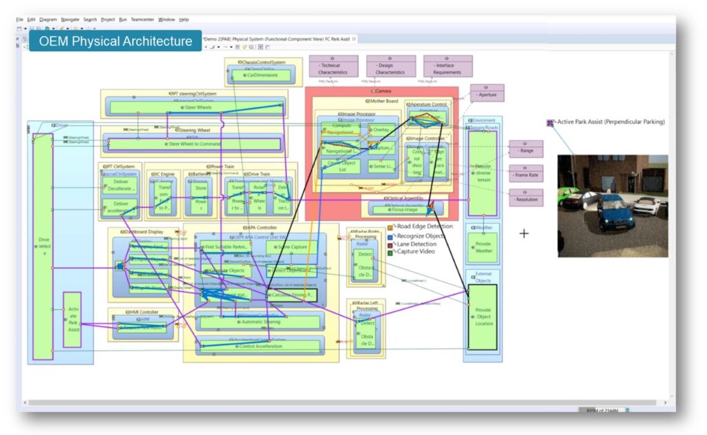
Finally, the OEM architect imports the developed ‘Camera’ module provided by the supplier through Teamcenter into the technology-specific physical architecture in SMW. The supplier provided-model shows the requirements traceability of the granular component requirements from the ‘Camera Spec’ provided initially by the OEM. Using the concept of Replicable Elements Collection (REC), a library of reusable components from the supplier model is created and is referenced to the OEM model. A Replica (RPL) of the ‘Camera’ physical component (red block in the picture above) is instantiated from the reference library in the system-of-systems architecture. A point worth noting is that the ‘Camera’ block in the physical architecture inherits the external functional chain interactions along with the interfaces defined initially on the ‘Camera’ as a black box. The architecture round-trip with the supplier is now successfully completed with the updated OEM system architecture ready for further analyses.
In this way, integrated supplier innovation in early OEM product development can provide a key starting point for establishing an extended MBSE enterprise, a Model-Based Design Chain. Including the suppliers right from the architecture definition stages allows you to integrate their expertise early to avoid late redesign/late cycle integration problems – saving significant costs and effort and a substantial reduction in product development life cycle. The case study demonstrates a streamlined approach to supplier innovation using a methodological architecture modeling workbench within the context of an open PLM environment enabling cross-enterprise decision support. The collaboration business process is supported by a secure, flexible mechanism with utmost prioritization to the OEM’s intellectual property and can be closely tracked to support monitoring and audit requirements.
It would not be a stretch of the imagination to conclude that product development in the Industry 4.0 paradigm will be like a playground that demands ingenuity in innovation, and those that innovate collaboratively will truly lead the game.
Your obvious curiosity at this moment might propel you to take a detailed look at the technologies mentioned in this post. Here is an on-demand webinar explaining the rationale for Model-Based Design Chain. Complement that with an example describing Siemens’ model-based approach to developing an integrated digital twin driven by a holistic system model as a starting point. Also, explore the fundamentals of the Architecture Analysis & Design Integrated Approach (ARCADIA) method used in this example that is integral to our integrated product architecture solution.