Reduce Time of irregular patterning with Clone & Duplicate commands – Solid Edge Assembly
It is usually required to create copies of parts in an assembly & this need is fulfilled in every CAD package but what makes Solid Edge special is clone and duplicate commands that breaks the boundary of regular patterns (rectangular, circular or along a curve) & helps in creating copies of parts wherever a target similar to the source is present.
Clone Component
Consider an example of a 6 cylinder IC engine, the cylinders are at different angles and require 2 valves to be inserted for each cylinder as shown below in fig.1

Fig. 1 6-Cylinder IC engine
As shown in the image above, there’s no regular pattern to pattern the valve at desired locations and manually inserting the valve at all locations followed by building assembly relationships will consume a lot of time. But this can be done by clone component command with great ease let’s see how?
Clone component is used where the component to be cloned has a refernce geometry(s) and target geometry(s) in different part(s). In our case the reference geometry is the cylindrical pocket where we have already applied assembly relationships between valve & engine & target geometries are other similar pockets as shown in fig.1
Using the Command
As shown below in fig. 2 the command has 3 steps
- Select the components to be cloned, valve in our example and click accept.
- Select the reference geometry in any other component, here highlighted pocket in engine head & click accept.
- Select all the components that has the target geometry identical to reference geometry, entire engine head here.
you will see all the pockets have the clone of the valve assembled. The other options include adaptable & exact copies as shown in fig. 2.
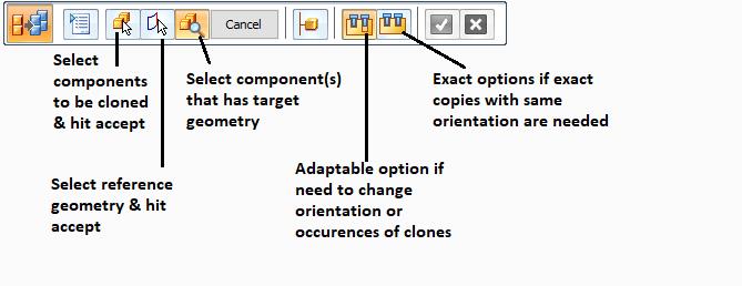
Fig. 2 Clone Component Command Bar
If adaptable option is selected you can keep or remove clones from required locations as per your selection & can also change their orientation. When preview of your clones is shown just before hitting accept to complete the command, notice pink spheres on each clone as shown in fig.4 below. Clicking on these causes a pop up to appear shown below in fig. 3
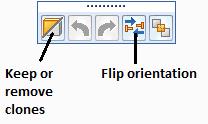
Fig 3 Adaptable Clone Options
You can click on keep or remove clones to add or remove selected clone & can also flip it’s orientation.
Note: You can select multiple clones to edit by holding control key & clicking on spheres of other clones
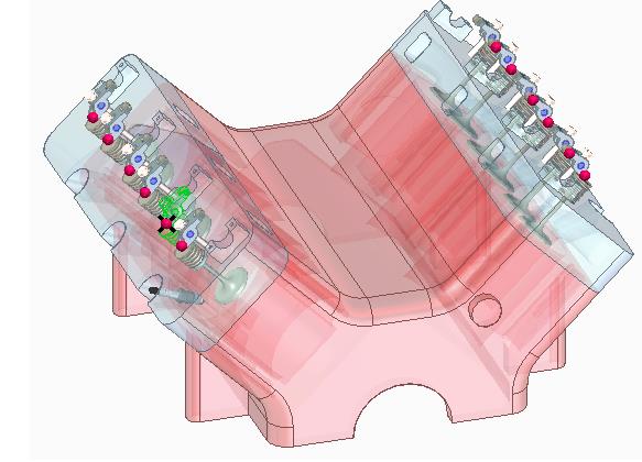
Fig. 4 Cloned Valves
Duplicate Component
This command is used when you have to attach copies of part(s) (with exact orientation & location) to other parts whose similar copies occur at several places in the assembly. Say for an example We have to attach nuts to all the bolts (identical) in the assembly. Note that all the bolts will be separate part files which is necessary in this case unlike clone command where a single component/ part file could have all target geometries.
Using The Command
This command is executed in 3 steps :
- Select the component to be duplicated and click accept.
- Select the reference component whose copies are present in the assembly.
- Click on target components or directly click on “find all matching occurrences” to find all identical copies of reference components in the assembly. This will show preview of the duplicated component at all locations, hold control key and click on any duplicate copy to remove it if not needed at that location else click finish.
The part has been duplicated at all locations. The command options are shown below in fig. 5

Fig. 5 Duplicate Components Command Bar